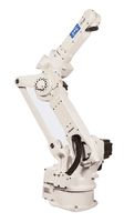
FD-A20
 |
| Type | FD-A20 | ||
| Kinematics | Vertical articulated type | ||
| Number of axes | 6 | ||
| Working Range (P-Point) | R 1664 mm | ||
| Max. payload capacity | 20 kg | ||
| Positional repeatability (*1) | +/- 0,07 mm (*1) | ||
| Drive System | AC Servo Motor | ||
| Drive Power | 7900 W | ||
| Working range | Arm | J1 (Revolving 1) | +/- 170° |
| J2 (Fore/Back) | -70° ~+ 60° | ||
| J7 (Revolving 2) | - | ||
| J3 (Up/Down) | -140° ~+ 240° (*2) | ||
| Wrist | J4 (Swing) | +/- 180° | |
| J5 (Bending) | -50° ~ + 230° | ||
| J6 (Twist) | +/- 360° | ||
| Max. Speed | Arm | J1 (Revolving 1) | 3,40 rad/s {195°} |
| J2 (Fore/Back) | 3,32 rad/s {190°} | ||
| J7 (Revolving 2) | - | ||
| J3 (Up/Down) | 3,14 rad/s {180°/s} | ||
| Wrist | J4 (Swing) | 6,98 rad/s {400°/s} | |
| J5 (Bending) | 6,98 rad/s {400°/s} | ||
| J6 (Twist) | 10,5 rad/s {600°/s) | ||
| Wrist load | Allowable Moment | J4 (Swing) | 43,7 Nm |
| J5 (Bending) | 43,7 Nm | ||
| J6 (Twist) | 19,6 Nm | ||
| Allowable Moment of inertia | J4 (Swing) | 1,09 kg/m² | |
| J5 (Bending) | 1,09 kg/m² | ||
| J6 (Twist) | 0,24 kg/m² | ||
| Ambient temperature and humidity | 0 ~ 45°C, 20 ~ 80 % RH (No condensation) |
||
| Weight | 355 kg | ||
| Upper arm payload capacity | 20 kg (*7) | ||
| Installation type | F, C | ||
Notes are marked with *.
Note 1: The value of the positional repeatability is at the tool center point (TCP) compliant to ISO 9283.
Note 2: The value in the parentheses indicates the wall-hung condition. J2 axis may occur the limitation of the working range.
Note 3: There are occasions where restrictions can be made to the operation range of the J2 axis when the wall-hung condition.
Note 4: The operation range of the J3 axis is restricted to -170 degrees to + 180 degrees when floor based welding is applied (In overhead mounting it's a combination of J2 + J3 axis).
Note 5: This is the specification for the case that the coaxial power cable are let into the centrum of J4 and J6 axis. The value given in parentheses presents for other specifications.
Note 6: There are occasions where restrictions can be made to the operation range of the J6 axis, depending on the J5 axis´s posture.
Note 7: Max. Load to the upper shoulder, when loading the max. payload capacity at the end effector.
F=Floor
W=Wall
C=Ceiling